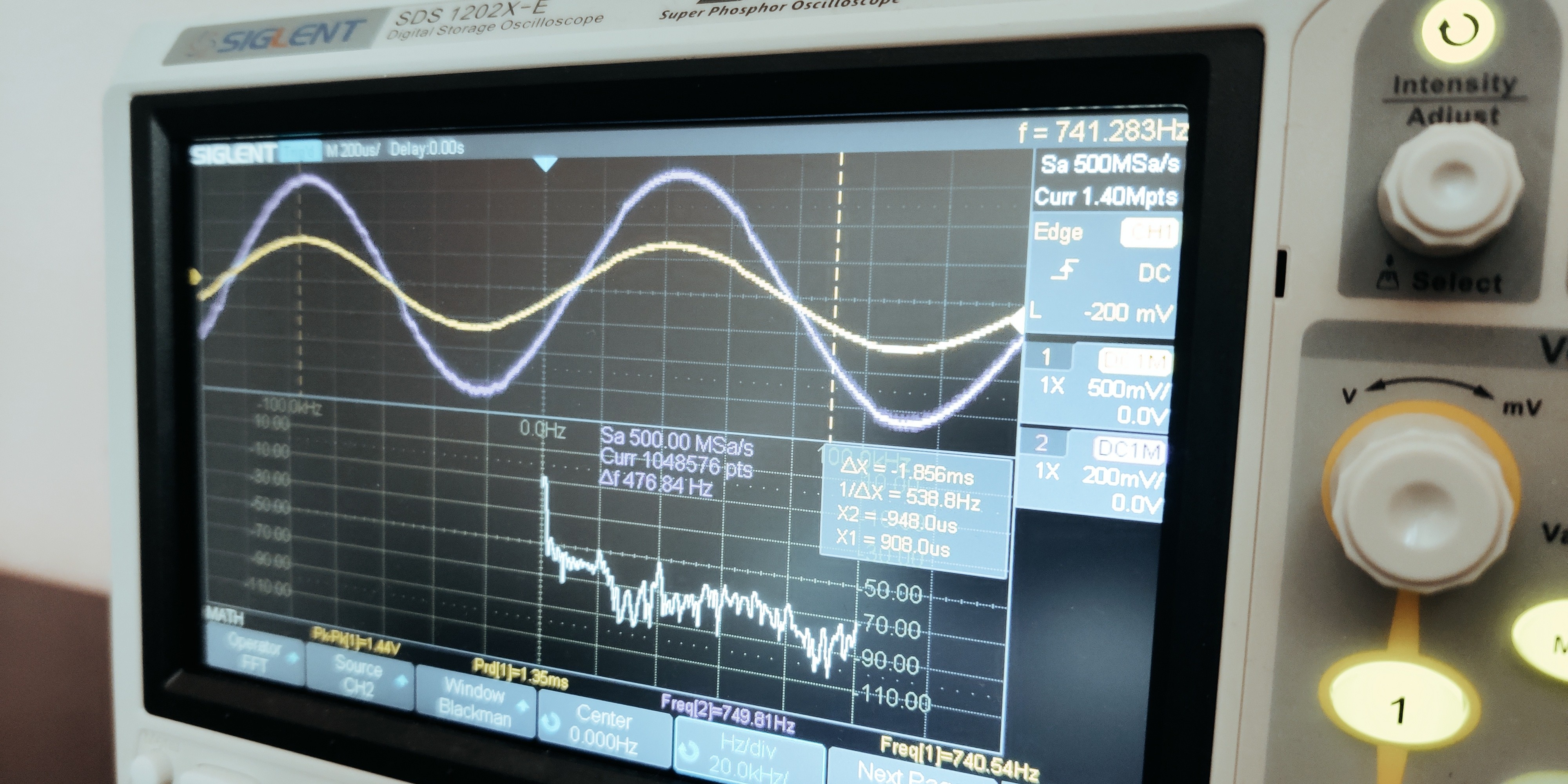
Picture of a sine waveform

Sine Synthesis with FPGA

Introduction Last time, we built a circuit together using Verilog to communicate with an I2S device. But we never delved into how to make a waveform for it. Now, don’t get me wrong: if you did the blinky LED example when starting your first projects, this should be easy for you: A square pattern is just zeros and ones A saw pattern is a counter from zero to max A triangle wave is a counter that goes back after hitting max or min values A sine wave is just some CORDIC… Now, we will not be using CORDIC and will not be doing simple counters. I want to show you a couple of tricks to generate a clean sine waveform that you can later compose to create fancier sounds. ...
June 15, 2025 · Daniel Blackbeard
Picture of some HDL code

Digital audio with I2S

Introduction As you may know, I’m working on this blog also as a way to log my learning journey. So, to make up for the lack of interesting peripherals on the Arty A7, I bought a set of modules for Arduino. Most of them were quite uninteresting, but I got this I2S DAC module from Adafruit that implements the UDA1334A from NXP (datasheet). This device interests me the most among the ones I got in the assortment, because ever since I was a kid I’ve wanted to make my own guitar effects (in fact, I believe many electronic engineers are born this way, or something similar), so the end goal is quite ambitious as you can see. But let’s start with something easy. ...

June 8, 2025 · Daniel Blackbeard