Introduction
Let me take a detour from the HDL and digital things and go back for a while into the analog domain. For this whole system I’m building to be of any use, the signal from the guitar has to have enough amplitude to:
- Dominate the noise of the processing chain
- Use as much of the XADC’s dynamic range as possible
In any case, I need something simple, while also thinking I wouldn’t be able to respect myself if I built it as a circuit mounted on a breadboard. So, I also took the chance to learn PCB production in a long afternoon.
But let me take things in order.
Preamp design
Again, something simple is good enough for this application. I don’t need accurate control of non-linearities, and although power consumption isn’t a hard concern, I still want to keep it low. Usual guitar pick-ups tend to have an output amplitude onto a capacitive load of around 10-50mV, so 20dB of gain is enough to avoid clipping and to make this stage dominate the noise figure of the chain. Volume control will be done in the instrument (guitar in this case) and digitally.
Also, I will need a pass-band that is adequate for audio, so a lower cutoff frequency below 20Hz and a higher cutoff frequency around 3KHz. Why not 20KHz? The guitar on E7 (last fret on the low E string) produces ~2640Hz; within audible frequencies it will have another 7 harmonics, which I’ve just decided to remove completely. Also, allowing more bandwidth than the average application uses means that the noise present at those unused frequencies passes through too (thermal noise has a white spectrum).
Additionally, the XADC requires a DC common-mode voltage at the input of 500mV. This means that the amplifier has to have a bias point at the output of 500mV, behave differentially, and have a decent rejection of supply noise.
So, let me summarize the specifications for this analog block:
| Spec | Value | Unit |
|---|---|---|
| Gain | 20 | dB |
| Low cut frequency | <20 | Hz |
| High cut frequency | 3K | Hz |
| V out (DC) | 500 | mV |
So, let me tackle the bits of design needed to come up with a complete proposal.
Circuit Topology
We will need a differential signal at the input of the XADC, but most guitars provide a single-ended signal. So we will need to use a topology that allows for single-ended-to-differential conversion.
This is a classical circuit in analog front-ends when it comes to optical communications:
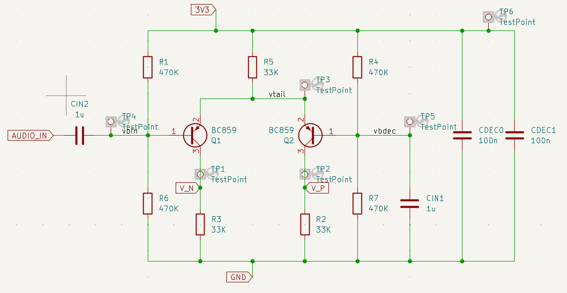
Schematic of a front end capable of single ended to differential conversion
If you’re familiar with analog circuits, this will look like a differential pair with a grounded input. It is. But to better recognize the single-ended-to-differential conversion, it’s more useful to look at this circuit as a regular common-emitter inverter that’s also an emitter follower, driving a common-base amplifier. This way, when you see the slight mismatch between single-ended gains, you won’t be all that surprised.
Choice of Component Values
In choosing the component values we have one important criterion: the output voltage has to be around 500mV. So whatever resistor we choose will also determine the current on the emitter of this amplifier, and vice versa. Let’s do some quick and dirty calculations and throw a few formulas that will drive the design. First, the emitter current will be approximately twice the collector current, hence
$$ I_E = 2\frac{V_{cm}}{R_C} $$
At the same time, the single-ended gain will be determined by a dirty ratio between the collector resistor and the small-signal emitter impedance:
$$ r_e = \frac{V_T}{I_E} $$
where
$$ V_T = \frac{K_B T}{q} $$
which is around 25mV at room temperature. Plug everything together and you get the small-signal differential gain:
$$ A = \frac{R_C}{r_e} = \frac{V_{cm}}{V_T} = \frac{500mV}{25mV} = 20 $$
Interestingly, this topology and the requirement of a fixed common-mode voltage impose, to first order, a gain of 20dB for each side, hence ~26dB differential, regardless of any choice of component or current (as long as it doesn’t break my quick and dirty formulas). Good enough, I will keep it.
However, the choice of current will impact the input impedance of the stage, and this input impedance, together with the decoupling capacitor at the input, will determine the lower cutoff frequency. Again, let’s do a quick and dirty calculation of the values required to meet the spec.
$$ Z_{in} = R_1 | R_6 | Z_{b} $$
where
$$ Z_{b} = \beta r_e = \beta \frac{V_T}{I_E} $$
with $\beta$ around 100 (typical for small-signal transistors), and let’s say around 15uA of current so as to not starve the transistors too much. $r_e$ ends up being in the range of 1.5KOhm, so $Z_b$ comes out around 150KOhm or more. Assume an overall $Z_{in}$ of 100KOhm. So, with a capacitor of around 1uF we get a cutoff frequency of
$$ f_{low} = \frac{1}{2\pi Z_{in} C} \approx 1.6Hz $$
All of this works given the availability of the components on my desk, hence the input cap will be 1uF, and I will stick with collector currents of around 15uA. So, if this is the collector current, that means $R_C$ has to be around 33KOhm. For simplicity, I’ll stick with 33KOhm on the emitter too, which will have a voltage drop twice as large. This means that with a supply of 3.3V, the $V_{CE}$ is 1.8V. This is plenty to keep the transistor in the active region when the swing on the collector goes down. The choice of emitter resistor, however, binds the choice of biasing resistors (mainly their ratio), since I need the emitter to be at ~2.3V — meaning the base has to be at ~1.6V. Interestingly enough, this will work with what I have, as I can make this ratio 1/2 the supply voltage and get 1.65V. Slightly more, which means more emitter current, lower input impedance, and a higher low-end cutoff frequency. Given the values already obtained, this might work for me.
There’s one last question to answer: the high cutoff frequency. The XADC has an equivalent input circuit like the one in the figure
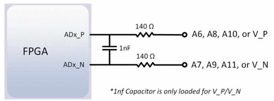
Model of XADC input impedance, from Arty documentation
So, we have those 33KOhm collector resistors being the main contributor to output impedance, with the 1nF capacitor. This leads to a cutoff frequency of
$$ f_{high} = \frac{1}{2\pi Z_{out} C} \approx 2.4KHz $$
I’m taking this value as well. If I weren’t happy about it and wanted to increase or decrease it, I would change the values of $R_C$ and $R_E$ while preserving their ratio until I get the frequencies where I want them to be. This would also mean fixing the base biasing voltage again. Usually an iterative process, aided by a simulator.
Simulation results
So, indeed, let’s see what the simulation says and how far I am from what I wanted.
First, a DC operating point (OP) simulation, checking the voltages at the different nodes:
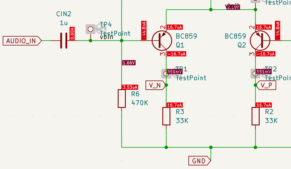
DC OP simulation of the preamplifier
We got a higher collector current, leading to a higher $V_{cm}$. Does this bother me? Not too much — I could tweak the emitter resistor a bit, but discrete components have some granularity, and it’s not really worth over-optimizing. The problem was indeed the ratio of the base biasing resistors — those extra 50mV added some emitter current. Nothing crazy. Let’s look at the small-signal behavior now:
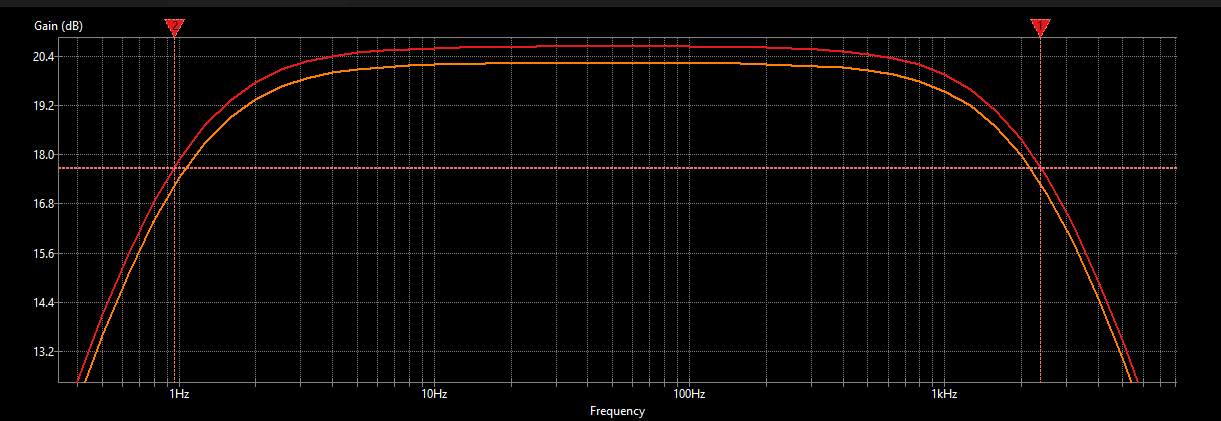
AC simulation of the preamplifier
The lower cutoff frequency is ~1Hz, good. The higher cutoff frequency came in lower than expected. This might be mainly due to overestimating the $r_c$ of the transistor and its associated parasitic capacitance. Again, I can raise the bandwidth a bit by tweaking the resistors, but this will work for my uses. Any needed emphasis can be done digitally if necessary.
I guess now you understand the meaning of “quick and dirty”.
One soft specification is the PSRR. I won’t go crazy optimizing this either, as it depends a lot on the circuit topology, but let’s characterize it.
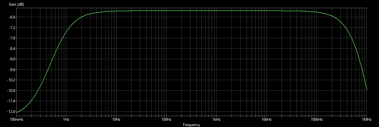
PSRR simulation of the preamplifier, single ended output
The single-ended PSRR won’t be that good, since the disturbance on the biasing resistors just gets split in half and then amplified by that same stage. However, in differential mode, this disturbance gets completely rejected (aside from mismatch issues in the components), because the differential conversion doesn’t happen on the other side of the amplifier (the AC-grounded base). Just trust me on this — values better than -80dB are easy to obtain, and the XADC itself will reject any common-mode disturbance anyway.
PCB design
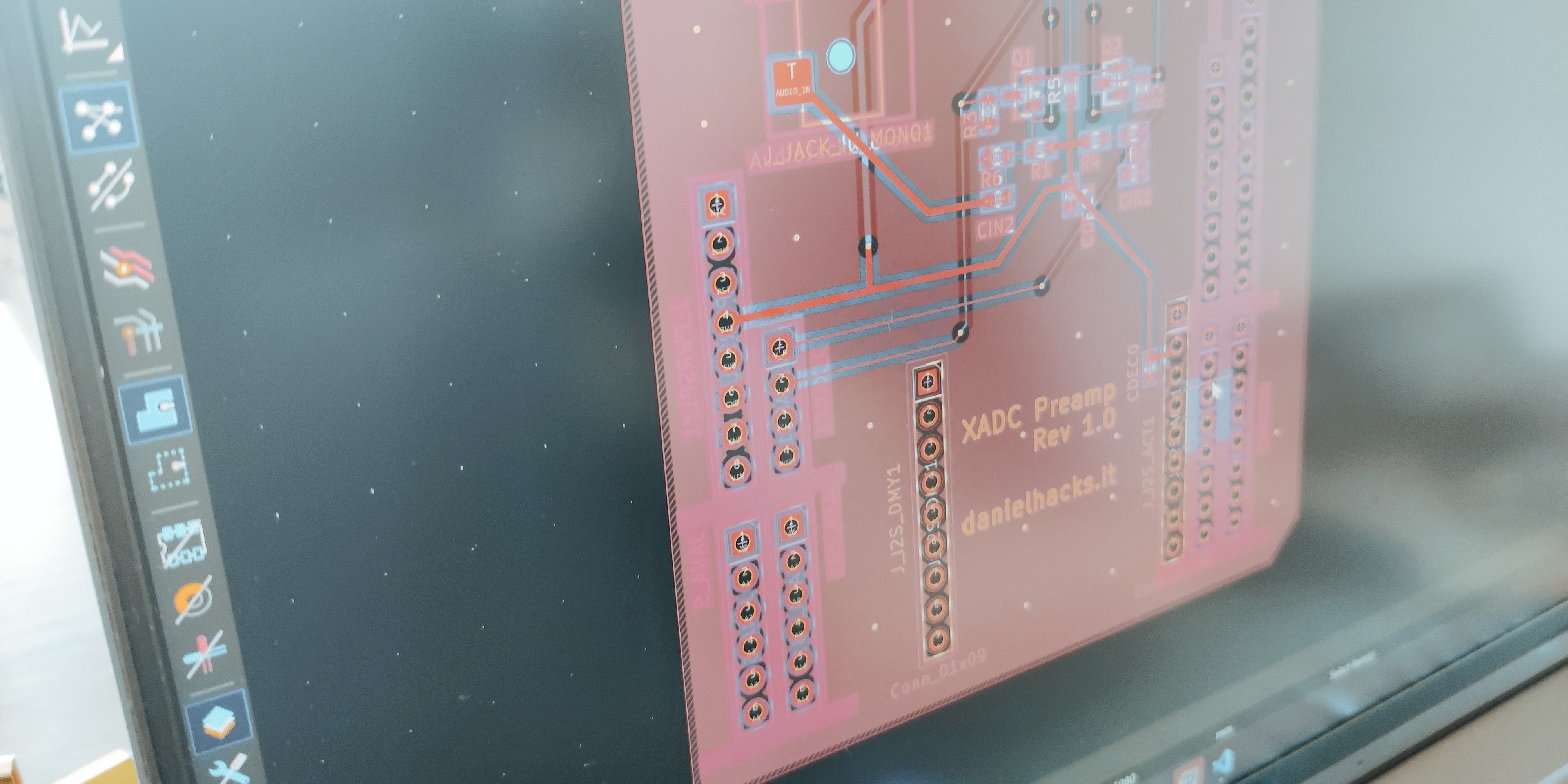
Let me be honest with you: since I was 12 years old and etched boards with iron chloride and Sharpies, I hadn’t made another PCB until now. All my design experience focuses on FinFET. So I wanted to take on the challenge and learn how to do this myself — given my experience in analog design, I expected this to be feasible, just a fight against the tool. Well, as you’ve probably noticed, I did my simulations with KiCad too, and I have to say I’m happy with this tool for simulation as well. In a few hours I went from nothing to a simulated design, and in another two hours — with some AI help for forum-related questions — I had my PCB. For now let me just show you a couple of choices I made, and I promise I will test it completely when I get my board back from the factory.
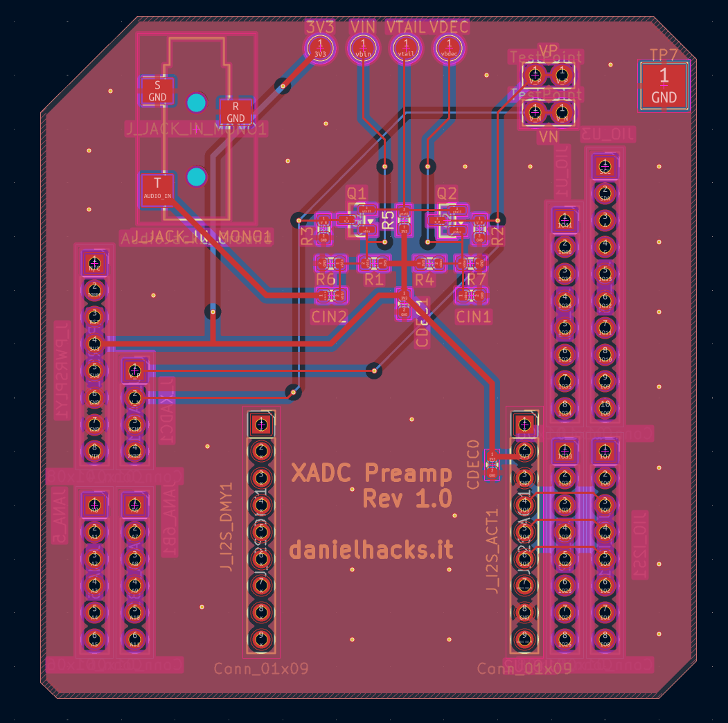
My first PCB design on CAD ever
First, there is the main part of the amplifier, with all the bunched components. I do this to reduce parasitic routing, but honestly I didn’t think much about the parasitic effect at the output (already underestimated). This will lower my bandwidth further, probably to 2KHz, but we’ll see. I also placed probe points for the different voltages, and points for the oscilloscope at the output (extra capacitance). At this point I’m thinking that if I’m not happy, I can always optimize the choice of resistors, but I won’t fret too much. No one really uses those very high frequencies while playing guitar (or I’m not skilled enough to do it anyway). There are headers meant to be compatible with the Arty A7’s headers, and two headers to hold the I2S module I used in an earlier blog post.
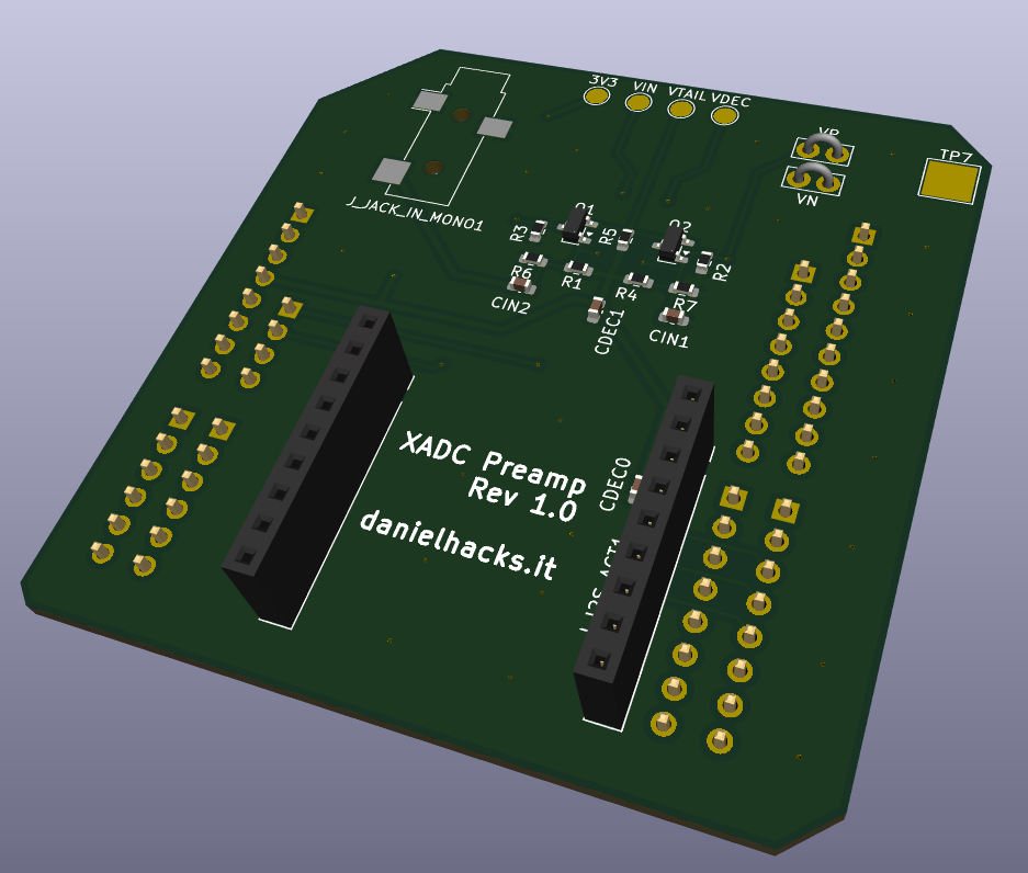
3D view of the PCB, not too shabby
Conclusion
This was a quick and dirty design of a preamp to be used as an analog front end for the Arty A7 XADC. A few things to improve, but I guess that’s the beauty of analog design. I regard it as one of the last artisanal jobs that managed to modernize into the space era.