Introduction
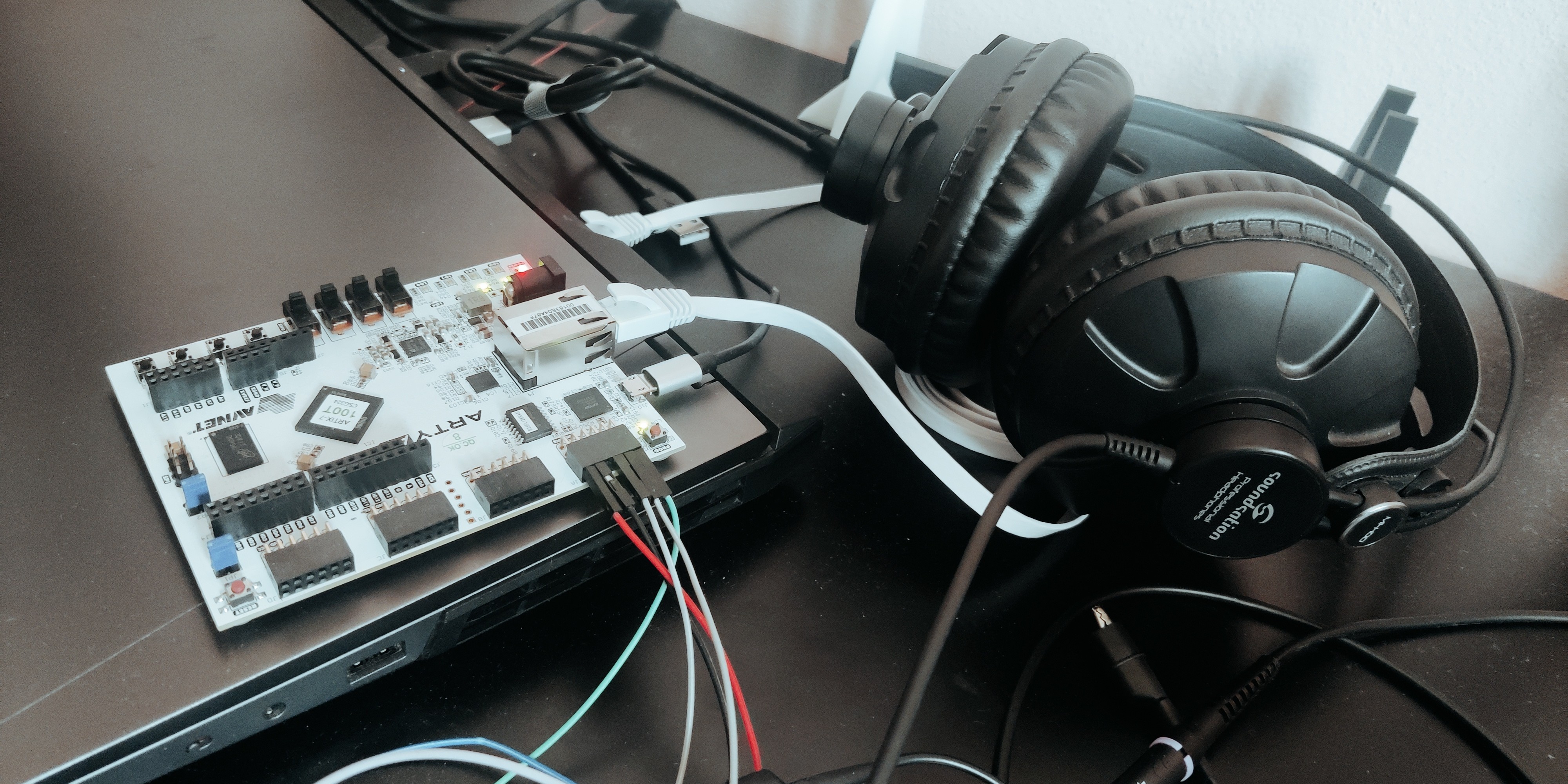
As you may know, I’m working on this blog also as a way to log my learning journey. So, to make up for the lack of interesting peripherals on the Arty A7, I bought a set of modules for Arduino. Most of them were quite uninteresting, but I got this I2S DAC module from Adafruit that implements the UDA1334A from NXP (datasheet).
This device interests me the most among the ones I got in the assortment, because ever since I was a kid I’ve wanted to make my own guitar effects (in fact, I believe many electronic engineers are born this way, or something similar), so the end goal is quite ambitious as you can see. But let’s start with something easy.
I2S protocol
I2S (not to be confused with I2C — it’s a different thing) is a serial protocol for transmitting audio that needs three wires:
- Left and Right selection, called Word Select (WS)
- Data stream
- A clock for sampling the data (BCK)
Those three elements have simple rules:
- The data stream has to be at least 8-bit (24-bit is best) of signed data
- The MSB is transmitted first
- The WS makes its transition during the falling edge of the BCK
- After the WS transition, the LSB is processed to give the receiver time to process the stream before switching to the other audio channel
So, basically the stream will look something like this: WS comes before the data stream ends
With this said, let’s take a look at a simple implementation in SystemVerilog for this circuit.
Implementation
From a module perspective, I want to make it very easy, with few requirements for the modules that will use this one. Hence, we will need a clock, the input data to be sent, the three outputs to the I2S receiver, and an invert flag in case I want to swap the left and right audio channels. The user of this module will be in charge of sending the data at the right moment, given the wide timing margin that the WS offers.
I will send 24-bit data at 48KHz because it’s easy. This way, I can start from a 60MHz clock I generate using a PLL in the Artix 7 FPGA, and use a strobe to generate all the other signals. A counter from zero to the division ratio will act as the state for the system.
The divisor has to be such that it takes the clock from 60MHz down to 48KHz audio, as mentioned before, but the streamed data is serial, so the BCK will have a clock frequency of 24bit x 2(LR channel) x 48KHz = 2.304MHz. Now, it just happens that it’s hard to make perfect ratios for the many clocks I plan to use, so I’ll settle for a divide ratio of 26, accepting a non-audible sampling rate at the UDA1334A of 0.16% higher frequency. Not a bad deal.
So, all together, this will end like this:
| |
Quite easy, as promised.
So, when the strobe is 6'b011001, the strobe is reset and the state is increased by 1. If the state is zero, it switches the audio channel; when the state is 1, it loads the next piece of data. The BCK is just a cheap 1-bit alternating counter, as generating it with a PLL isn’t possible.
In simulation, we can obtain this: A stream of 24’hE38E38 is sent here
Conclusion
This piece of Verilog, together with an I2S-capable device, will allow you to send pieces of an audio waveform out to the external world. This is the first step toward making a small synthesizer (in the next post) and, in the future, a complete digital audio processor.
If you want to get the sources of these blocks, as I write this blog I’ll place them at my GitHub repo