Introduction
So, after you’re done with the book and have implemented your first 8-bit CPU, you keep wondering
ok, but now I want to do real-world stuff
I’ve got you covered — when it comes to real-world stuff, nothing beats having the capability to send data to and from other devices. When I began my personal projects, right after getting my Arty A7, I thought I’d need to debug what’s happening inside the FPGA in case the internal logic analyzer wasn’t reliable (pro tip: it’s very reliable). So being able to send data to a computer using a simple protocol is a must.
UART comes out as the best option for easy communication, as the baud rate isn’t so high that it needs complicated timing analysis, but it’s complex enough to be a fun first project for learning the basics of digital design applied to the real world, with real constraints and specifications.
What is this UART then?
UART (universal asynchronous receiver-transmitter) is a serial communication protocol that doesn’t require tight clock sync between transmitter (TX) and receiver (RX). Basically, the TX pulls the wire down to tell the RX that it needs to start listening, sends some bits of data one at a time, maybe some parity bits, and ends the transmission by setting the wire high. Indeed, the wire is at rest when it’s kept high.
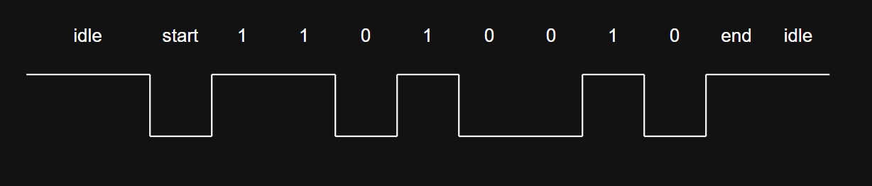
Example of UART signal
As you can see from the picture, 8 bits are sent, no parity bit is sent, and there is a starting signal (pull down) and an end signal (pull up). The transmission is idle when the wire is kept high. The other condition is that the least significant bit (LSB) is sent first. For example, in the transmission above, the byte 8'h4B is sent starting with the h4 symbol reversed, followed by the hB symbol, also reversed.
How do I implement the UART thing?
Even before writing a single line of code, let’s lay down a strategy for how to build this block and also how to verify it.
Functional blocks
So, for the UART we have the transmitter (TX) and the receiver (RX). These blocks should behave such that, when a signal enables communication, they start processing in a blocking way — meaning they process one byte at a time and notify when that’s finished so the next one can start. From a top-level perspective, we have then:
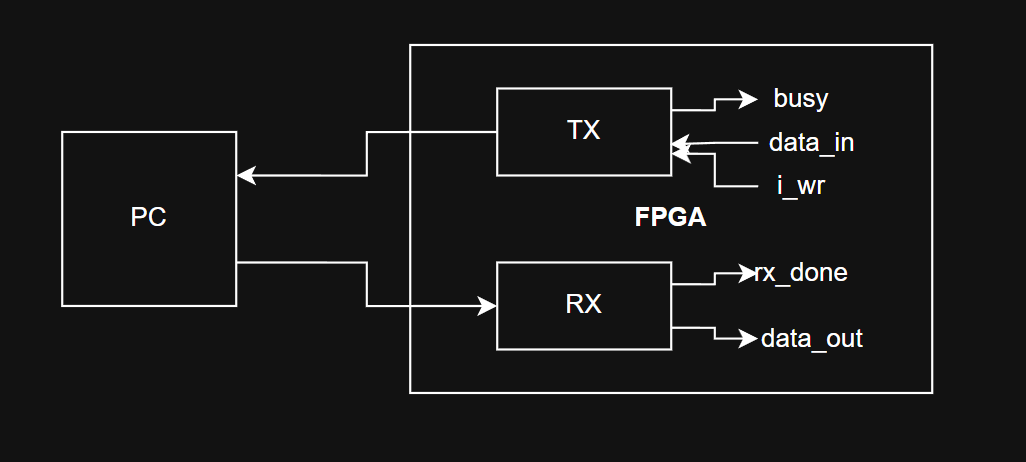
UART blocks
Basically, we will need two blocks: the TX, which gets the data and the starting signal and returns the UART stream to the PC along with a notification when it’s done; and the RX, which gets the incoming stream from the PC, notifies when it’s done, and provides the data at its output.
How do I verify this is working?
We will have to prepare a testbench where we chain some UART input data, use the RX to decode the stream, then send this very same data to the TX. The expected result should be a UART stream that’s equal to but delayed relative to the input signal — easy enough to verify, but since I’m kind of lazy, I’ll chain another RX instead, and make sure that the chain data -> RX -> TX -> RX yields the same decoded data.
So, let’s look at the details of each block now
TX
The TX, as shown in the picture above, takes input data from a register and a command to start transmitting, then raises a busy flag while it’s serializing the data — telling whatever FIFO (or other source) is feeding it data not to send any more until the flag is lowered. However, the TX should be ready to start again as soon as it’s finished. This is where the stop bit helps: while it’s held high for one period, the TX gets ready to receive the next byte of data.
To do this, we will rely on a finite state machine (FSM from now on), which indicates what step of the process the transmitter is at. We’ll also give the block the baud rate for the transmission, and since I’m using the Arty A7’s clock (100MHz) for this particular example, I’ll set it as a parameter. The goal is to tell the circuit, via a counter, how many clock cycles each period of the UART signal requires before transitioning to the next state.
| |
The strobe signal is this counter, and when it reaches the required number of clock cycles, it resets and commands the next state to take over. Also, you can see I’m not explicitly defining a separate final state, since I’m treating IDLE as that state too — one that’s already able to receive commands for the next byte to transmit.
For the sake of verification in simulation, I set an initial value for some variables. Those lines aren’t necessarily synthesizable, but they’re of great help and will save a lot of debugging later in simulation. Then, the main process is placed under a flip-flop (that posedge mixed with reg in its content). As you can see, when the strobe reaches zero, the state is updated, the counter is reset to the value of DIVISOR, and the output is set to the newest bit — otherwise it keeps counting down. Another feature: if we’re in the IDLE state we don’t count, the circuit is frozen. This isn’t that useful, but I don’t like polar bears swimming around Italy because of global warming.
| |
Finally, we define the transitions of the state machine and raise the busy flag whenever we are busy processing data. Also, notice we are updating temp_buf as a shift register. This is another subtlety, as it’s more expensive to place a big mux in front of the array than to just shift the data and take the last bit. This also helps with filling in the 1'b1s that pad out the stop condition.
| |
So there you go — as promised, an easy block, just a few lines of HDL that stick to basic rules of digital design. Now let’s take a look at the receiver.
RX
This block isn’t much more complicated, but it has a subtlety: a real line, when idle, can for any reason — noise, crosstalk, electromagnetic interference, etc. — be pulled into a low state. This is a false positive for the start of transmission and we don’t want to catch it. Also, unlike the transmitter, we want to sample the data not at the beginning but at the middle of the UART period. This is because you never know the quality of the signal you’re receiving, and if the cable is very long, lossy, or doesn’t have enough power to drive the RX input capacitance, the signal might not settle correctly if we don’t give it enough time.
So, in the same way as before, we define some parameters for the baud rate, the initial value of some variables, and the states of the RX:
| |
Here’s the logic for the state machine. Same as before, if the state is IDLE we just stop the counter. Here, we also define the rule for updating the output in a way that hides the inner process, setting it to the final value only when we’re about to set the state to idle.
| |
Finally, the update rules for the FSM: we set the rx_done flag to one, but only for one clock cycle. This is so I can chain an RX and a TX and make echo requests with the UART. Also, notice that we set next_state at the midpoint of the counter, for the reasons given at the beginning of this section.
| |
Simulation
For testing this block, I will feed the RX with some premade data stream, and chain RX to TX to RX and check the values of the processed data and the UART signals. Also, via parameter, I will set the baud rate of the UART to 25Mbaud, so that the counter needs to count 4 clocks and the simulation doesn’t get too long.
| |
The resulting signals are as follows:
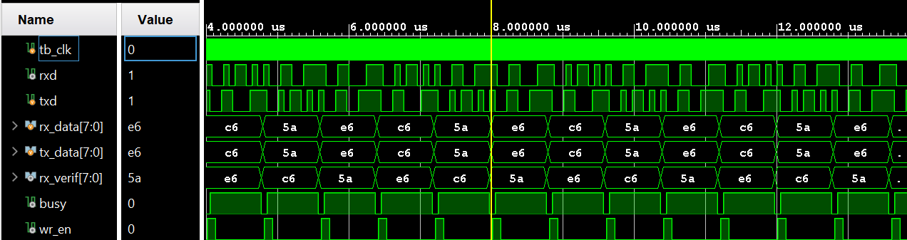
UART Simulation in Vivado
In the picture you can see the RX receive the stream defined in reg [29:0] pattern, and once it’s done it passes the data directly to the TX. The TX then processes and sends the data to the verification RX, hence there is a delay from TX to verification RX of about 9 symbols, without wasting clock cycles between one byte and another.
Conclusion
Together with you, I’ve built the first block on my Arty A7 that I’d consider a complete project. It passed a full run of simulation, and when implemented on the FPGA the echo functionality works. My next step is to stress-test this block by making a loop and sending pseudo-random data while checking the bit error rate.
If you want to get the sources of these blocks, as I write this blog I’ll place them at my GitHub repo