Introduction
If you’re a hardware engineer you need no explanation — this is more for the programmers who try to build things with an FPGA, believing it’s the next step up from Arduino. (I happen to agree, so no judgment here.)
As someone who wrote a lot of code in my youth (and still loves fiddling with the Linux kernel), I’m lucky that I understood the purpose of HDL early on.
Given how many times I’ve seen this question raised on Stack Overflow or Reddit, by programmers struggling as they approach the field of digital design, it’s not a wasted question. So what even is HDL?
What is HDL?
Basically it stands for Hardware Description Language. Still a language, but not for programming on a Turing machine.
So, for the software folks — the ones who do real programming, meaning you know at least Lisp, preferably Haskell — this is a kind of functional language. It is actually a netlist language, where you describe the connections of digital circuitry: the inputs to the block (HDL module) and the outputs that go somewhere else. This pretty much resembles the behavior of functions (zero or more inputs, at least one output). So, if you know your functional languages, you will fare very well with HDL. Otherwise, I pretty much recommend Haskell as your next step for building programming muscle.
In this blog I will mainly write in SystemVerilog, a superset of Verilog, which is one of the most popular hardware description languages. The other one that’s out there is VHDL. As usual, both are capable of getting the job done — it’s mostly a matter of preference (or whatever you’re forced to use at your workplace).
What are this wire and reg?
In logic design you have ones and zeros. Sometimes you have a floating piece of metal not connected to anything, or something whose current state you simply can’t tell when you plug in a supply (remember, we’re still talking about circuits — forget definite initial states).
A wire is an element that, like a real wire, can carry information from point A to point B. That’s all. In HDL, you need to define wires so that you can differentiate the connections from one module to another by their labels. Here’s an example:
| |
Let me reiterate once again: we are dealing with logic, which is akin to functions (some inputs, at least one output). With wires, we define where this and() element (the circuit for the logic AND operation) is connected — and to what.
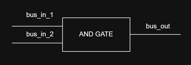
They are just labels you use to identify connections
Instead, reg is like a wire that can also store its state — a memory element. This is often where the confusion comes in, as a wire isn’t a complicated circuit, just a piece of conductor. Whatever gets synthesized by a reg, on the other hand, ends up having some transistors. Hence, a reg will synthesize either a latch (a memory element that’s dependent on the level) or a flip-flop (a memory element that’s dependent on the transition of a control signal, almost always a clock).
If you don’t know what latches or flip-flops are, here is a brief explanation:
A latch is a memory element that sets the output equal to the input when actively driven. When no driving is given to the latch (no electrons in the input, or floating input) it preserves the last state. A flip-flop will propagate the state of the input to the output only when a transition either from zero to one (rising or positive edge) or from one to zero (falling or negative edge) happens.
As a general rule, in digital design you avoid latches as they are very technology-dependent in their implementation (they can be very power-hungry sometimes). From now on let’s set the rule that we will try to synthesize only flip-flops.
They said HDL has intrinsic parallelism
HDL is as parallel as two logic gates working at the same time. You describe the logical circuits and nothing stops it from making two operations at the very same time (disregarding propagation delay in logic gates). In this way, the parallelism is really explicit.
So can I do a for loop?
Hardware Description Language!
Try to make a for loop out of AND/OR/NOT gates on a breadboard. Sure you can, but there are better ways to make a loop that saves components (fewer components, less area, less power wasted, polar bears not floating around Sicily).

Yup, when you shitpost on reddit global warming send beards to Sicily
However, for all intents and purposes, HDL is capable of parsing a for loop, as it will infer the engineer’s intent and generate the equivalent circuit that reproduces that behavior. You can pretty much describe the behavior of your circuit in HDL, with no guarantee that the synthesis will be the best one for a certain algorithm.
Again, team Haskell wins here against team Java (lol). Recursion is basically a way of making pipelines in digital design.
So, am I ready to write HDL after reading this?
Let’s be honest: you were always ready to make digital circuits, just that your mindset was obfuscated by the prejudice that HDL is a programming language. Now that you know it isn’t, and you know that it basically describes the connections and/or behavior of logical circuits, the doors are open for you. But for the sake of building a framework that will let you make good designs, let’s lay out this set of rules:
- When using
always @(posedge clk)oralways @(negedge clk)to create flip-flops, always strive to use real, unconditional clock signals. Avoid other signals as much as possible. - Never synthesize latches. The synthesis tool usually reports when this happens, but a basic rule is to never put a
regvariable under analwaysstatement that doesn’t contain eitherposedgeornegedge. - Avoid
fororwhileloops as much as you can — the better you get, the less you’ll need them. - Abuse
case(variable)whenever you can. - Avoid combinational loops. In HDL everything happens at the same time, so something like this
| |
will fail miserably as you just created a ring of buffers